
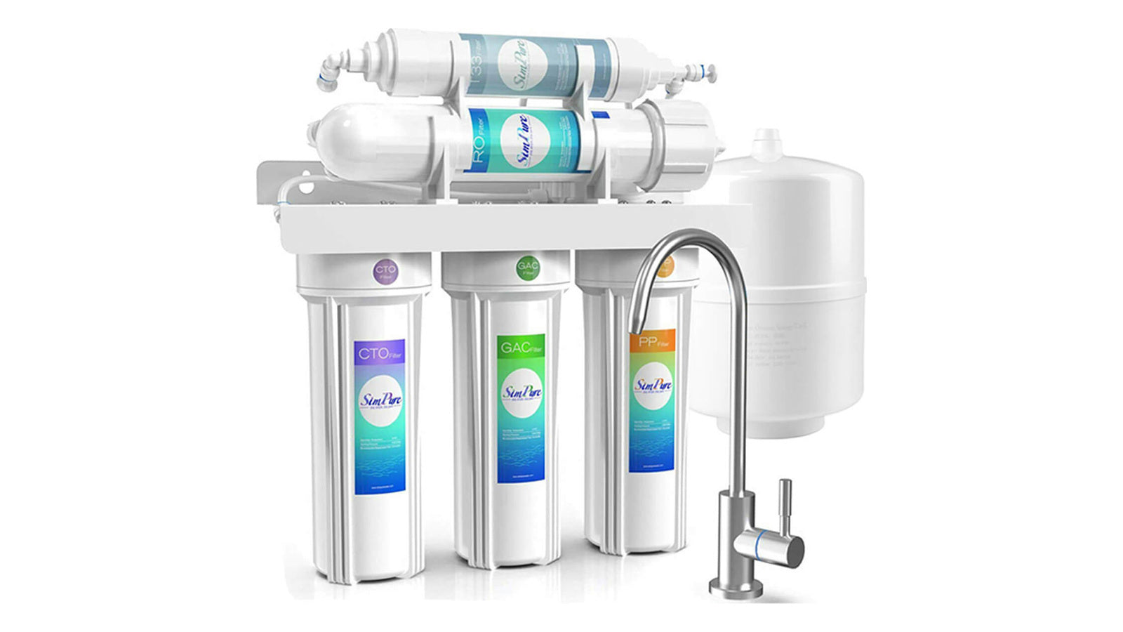
Do not begin a reverse osmosis system installation by drilling a faucet hole. First lock the exact model and manual, confirm that the site has the right feed water, drain, space, and—when required—power, then draw every connection before cutting tubing. Install from the water source toward the faucet, pressurize slowly, test in both static and flowing conditions, and complete the model-specific flush before using the water.
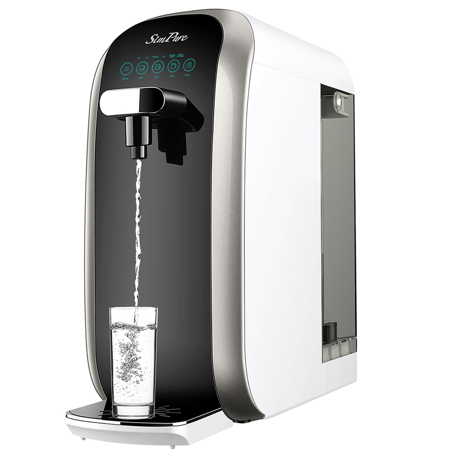
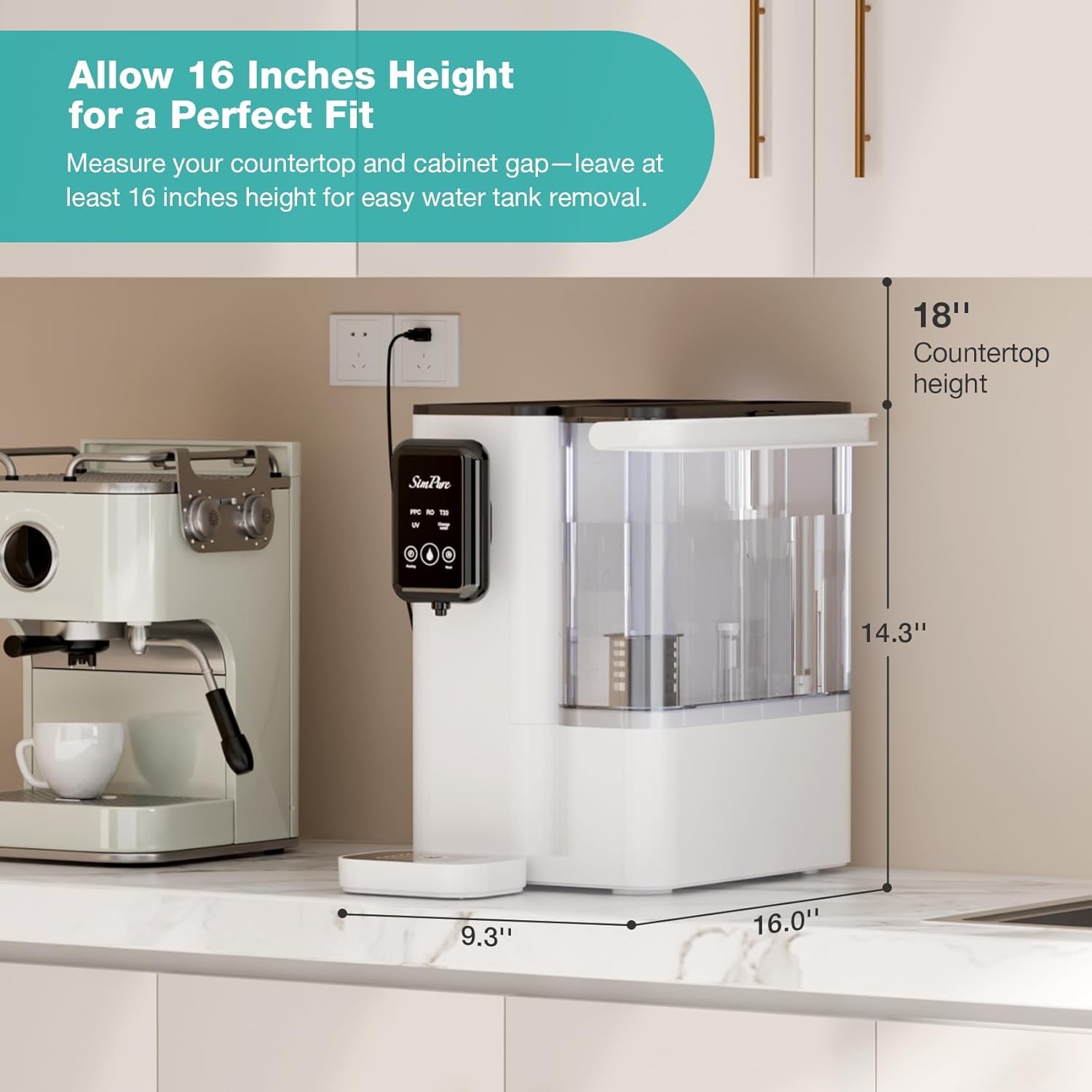
That sequence matters because “RO system” does not describe one plumbing layout. A countertop dispenser, a tanked under-sink unit, a powered tankless unit, and a point-of-entry system have different boundaries. Stage count does not tell you whether you need a storage tank, drain connection, outlet, or new faucet opening.
Start with the installation family, not the stage count
The U.S. EPA defines a point-of-use RO system as one connected to a single fixture. This guide focuses on household point-of-use installations. A whole-home or point-of-entry project changes pipe sizing, flow, pretreatment, drainage, and code questions enough to require a separate design.
| RO format | Usual site interfaces | Installation consequence |
|---|---|---|
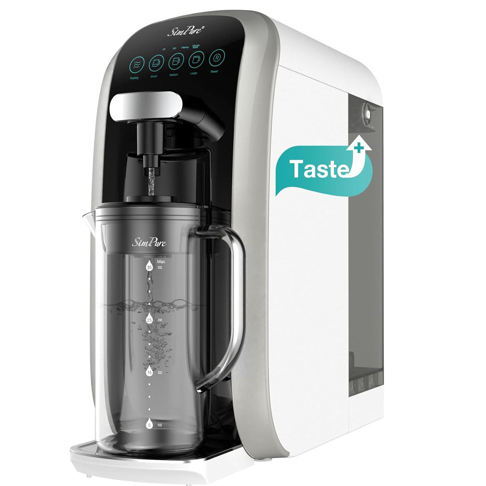
| Countertop reservoir | Counter space, power, manual filling and concentrate handling | No permanent sink plumbing for many models, but setup and flushing still follow the exact manual. |
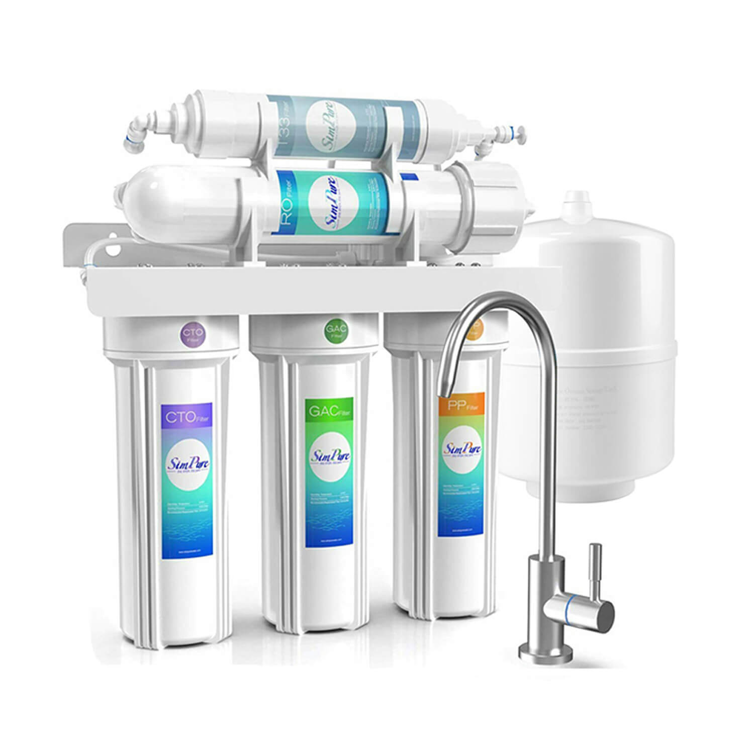
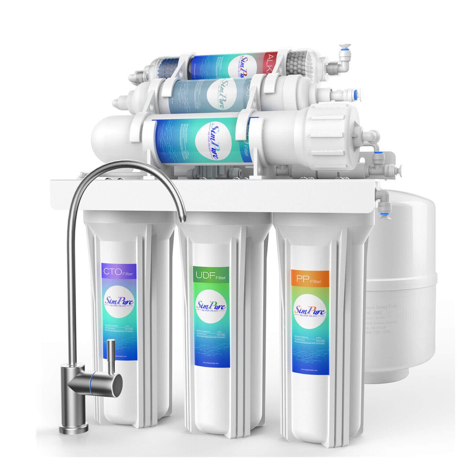
| Under-sink, tanked | Cold-water feed, treated-water faucet, drain and storage tank | The cabinet must hold both the treatment train and a serviceable tank without pinching tubing. |
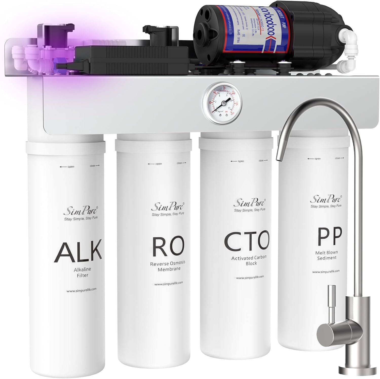
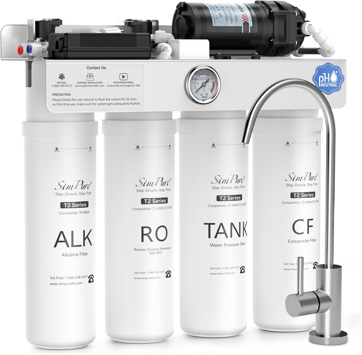
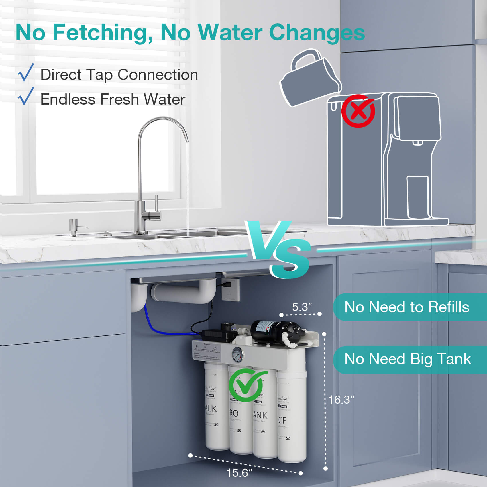
| Under-sink, tankless | Cold-water feed, treated-water faucet, drain and often power | It may save tank space, but an outlet, pump clearance, and model-specific operating limits can become new gates. |
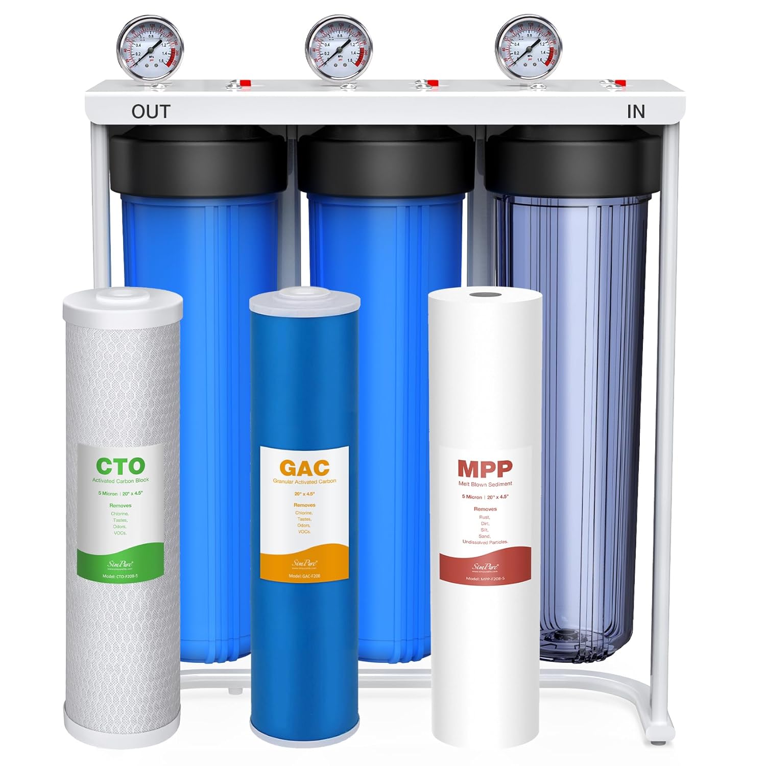
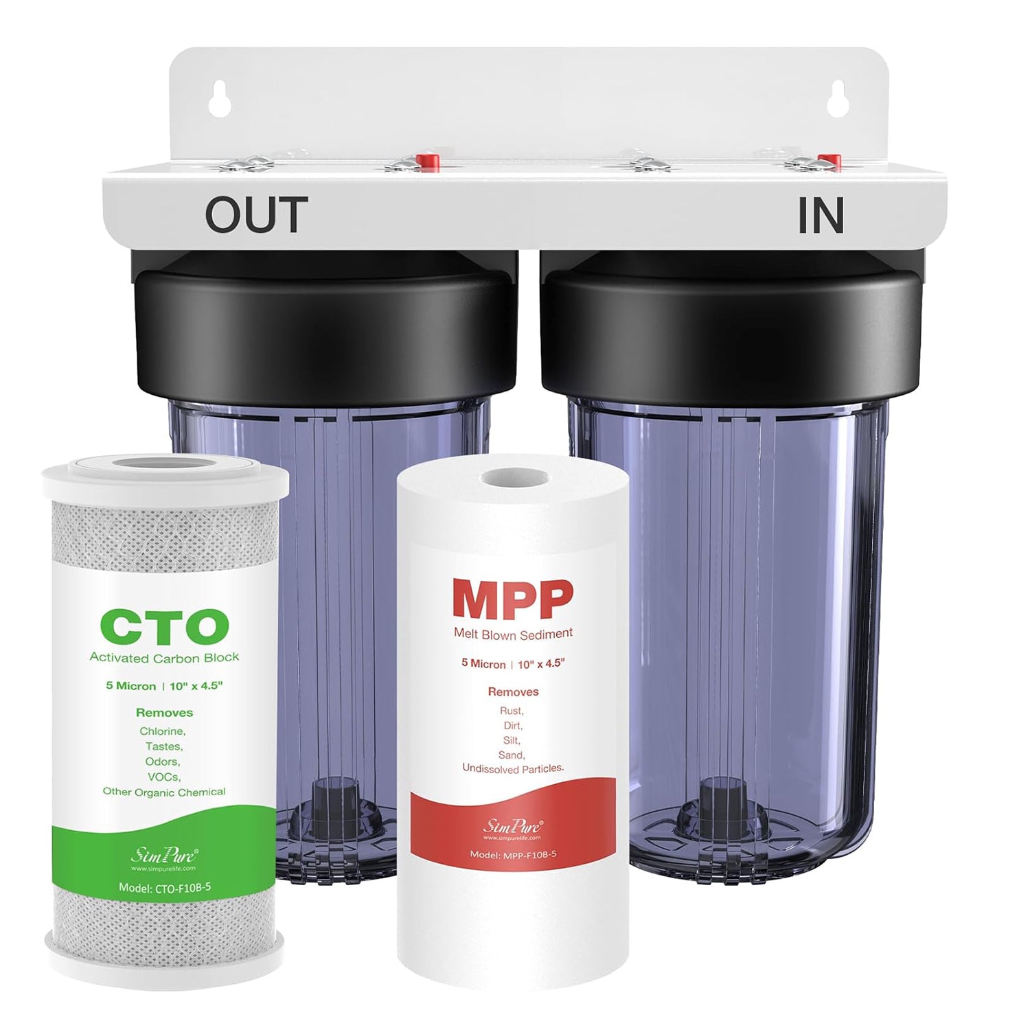
| Point-of-entry | Main line, pretreatment, high-capacity drainage, controls and distribution plumbing | Treat this as a designed plumbing project rather than an enlarged under-sink installation. |
If the separation process itself is unfamiliar, read the RO mechanism guide first. Knowing which line carries feed water, treated permeate, and concentrate makes the installation map much easier to audit.
Pass five preflight gates before opening the kit
A successful site passes all five gates below. “The unit fits under the sink” is only one of them.
- Feed-water gate: Match the source, pressure, temperature, hardness, TDS, and any pretreatment requirements to the exact manual. Do not transfer an operating range from another model in the same product family.
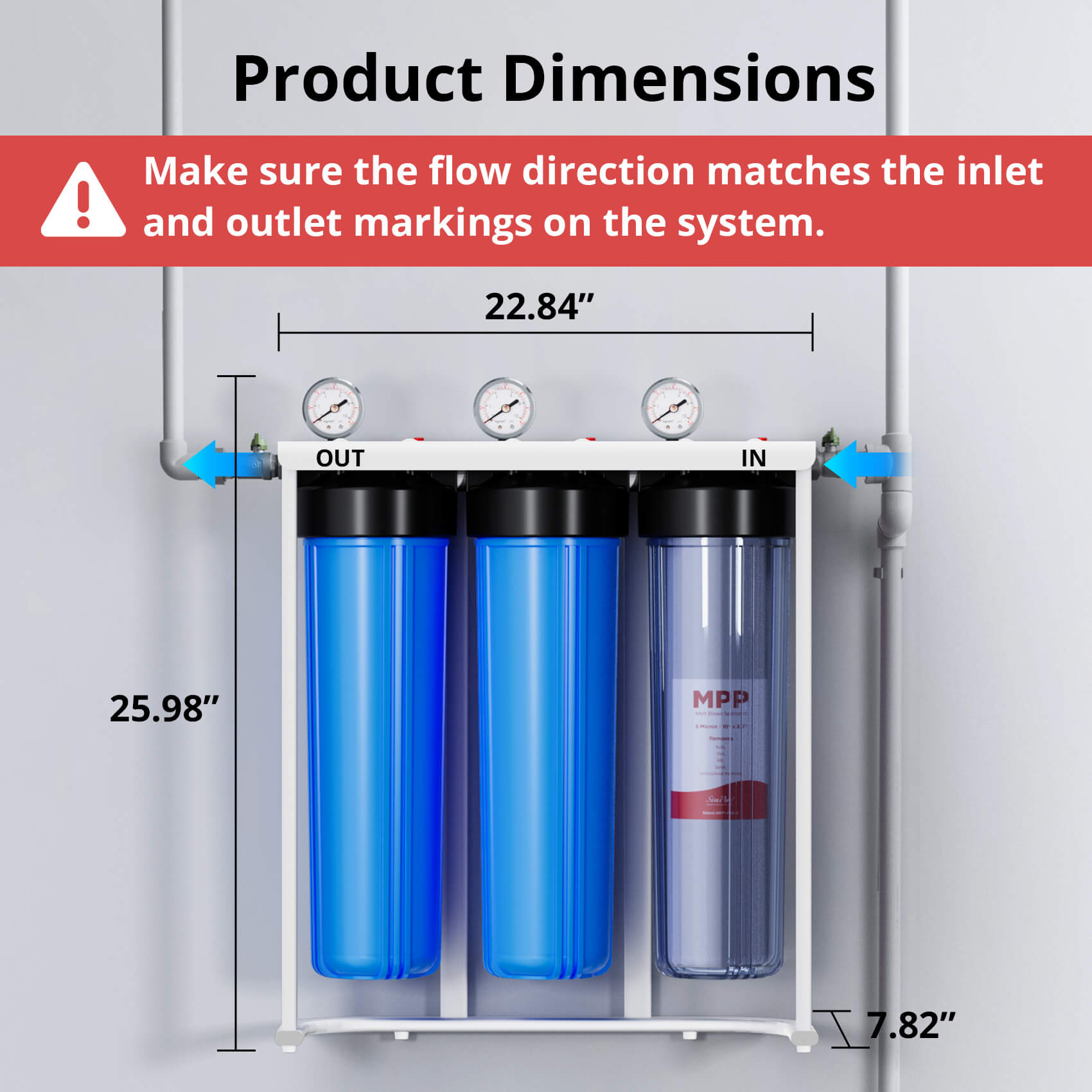
- Space and service gate: Measure width, depth, height, door swing, and the clearance needed to remove cartridges. Protect the unit from heat, freezing, direct sunlight, stored chemicals, and items that can strike tubing.
- Plumbing gate: Identify the cold-water shutoff and connection size. Confirm that the valve works before disassembling anything. A corroded, seized, or leaking shutoff is a plumbing repair, not an RO accessory problem.
- Drain and code gate: Find the exact permitted drain connection and its position relative to the trap and disposal. Drain saddles or air-gap arrangements may be restricted by local code; the included part does not override local requirements.
- Faucet and power gate: Confirm an approved faucet opening or a drillable surface, plus the outlet specified by the manual for powered systems. Do not assume stone, tile, composite, metal, and porcelain use the same bit or drilling method.

The current SimPure manual library illustrates why model identity matters. Its listed T1-400 series manual shows a powered, tankless topology with a cold-water feed, separate faucet, drain line, and model-specific operating limits. The listed T1-5 manual covers a traditional tanked configuration. They are both under-sink RO systems, but they are not interchangeable installation instructions.
Draw the line map before cutting one tube
Lay the parts on a clean surface and create a simple connection ledger. Use the port labels in the manual—not a color remembered from another installation.
| Connection | From | To | Pre-cut check |
|---|---|---|---|
| Feed | Cold-water adapter or approved feed valve | System inlet | Valve size, washer or O-ring position, tubing route and shutoff access |
| Treated water | System outlet | Dedicated faucet, tank, refrigerator kit, or other manual-approved endpoint | Correct branch order, compatible tubing, pressure requirement and backflow provisions |
| Concentrate | Drain or waste port | Approved drain connection | Position relative to trap/disposal, code compliance, downhill route and no kinks |
| Power, if required | Specified receptacle | Pump and controls | Voltage, cord reach, dry location and local electrical requirements |
| Storage tank, if fitted | Manual-designated treated-water branch | Tank valve | Stable upright location, service clearance and correct precharge procedure |
Mark both ends of every run. Cut tubing squarely with the approved cutter, remove burrs, and insert it to the depth specified for the fitting. A tube can look connected while stopping before the internal seal. Pull back gently after insertion only if the manual calls for that check.
Install in a controlled sequence
The following sequence is a planning map, not a substitute for the model manual. If its order or fitting details differ from the instructions in the box, stop and use the current instructions for that exact revision.
- Inventory and photograph: Match the unit, cartridges, valves, adapters, tubing, faucet, tank, clips, seals, and power supply to the packing list. Photograph the unopened layout and existing plumbing.
- Make the area safe: Clear the cabinet, protect the floor, turn off the cold-water supply, relieve line pressure at the faucet, and disconnect power in the work area.
- Place before fastening: Dry-fit the system, tank, faucet, and tubing paths. Leave room to close the door, operate shutoffs, read indicators, and change every filter.
- Install the feed interface: Use only the adapter, sealing method, and orientation specified for the actual valve and hose. Avoid excessive force on plastic or small threaded parts.
- Install the dedicated faucet: Reuse a compatible opening when possible. If drilling is required, verify the surface material, hole size, clearances above and below, and who is qualified to drill it.
- Create the approved drain connection: Follow the manual and local plumbing rules. Keep the concentrate line free of sags, sharp bends, compression, and routes that can backflow.
- Mount and connect: Secure the unit as directed, seat cartridges in their labeled positions, make the feed, treated-water, drain, and tank connections, and install every locking clip supplied.
- Pressurize slowly: Keep the treated-water faucet open if directed, then crack the feed valve open gradually. Watch each joint rather than leaving the cabinet.
- Connect power only when instructed: For a powered model, confirm that the wet-side assembly is complete and the outlet matches the manual before energizing the unit.
- Flush and commission: Use the model's exact startup sequence, discard requirement, and flush duration. Record completion rather than assuming the first clear glass means the system is ready.

Prove the installation in three operating states
One quick look is not a leak test. Different failures appear before pressure, under static pressure, and only while water is moving.
| Test state | What to inspect | Failure it can reveal |
|---|---|---|
| Dry visual check | Port labels, tube depth marks, clips, seals, unsupported weight and kinked routes | Misrouting or incomplete assembly before water can hide the mistake |
| Static pressure | Feed adapter, housings, tank valve, faucet base and every quick-connect; use a dry tissue to expose a slow weep | Seal, thread, or insertion failures that leak while the faucet is closed |
| Flowing and draining | Treated-water flow, pump behavior, drain route, noise, vibration and cabinet movement | Restricted tubing, drain backpressure, loose mounting or faults that appear only during production |
Repeat the static inspection after the system has cycled and again after the first day of normal use. Keep the cabinet floor dry and visible during this period. If a joint continues to weep after correct reseating, shut off the feed and replace the damaged tube, fitting, or seal—do not conceal it with adhesive.
Startup is part of installation, not cleanup
New filters and tubing may require flushing to remove preservation liquid, trapped air, or loose carbon fines. The required sequence differs by model and by whether a tank must fill and be discarded. A fixed “flush for several hours” rule is no safer than skipping the step; follow the current manual and restart the procedure after filter replacement when instructed.
Operational checks also have limits. A TDS reading can help confirm that an RO membrane is producing a different dissolved-solids result from the feed, but it cannot prove that the water is free of every chemical or microorganism. CDC guidance advises testing the water and checking the exact system label for the chemicals or germs of concern. Installation does not expand a model's verified contaminant claims, and filtration does not override a boil-water or local health advisory.
Build installation cost from site changes, not a national average
The defensible cost equation is:
Installed cost = system + required interfaces + site modifications + labor + commissioning and correction allowance.
A national price range hides the variable that matters most: what must change at your sink. Build or request an itemized estimate with these lines:
- the exact RO system and any tank, refrigerator, air-gap, regulator, or pretreatment kit;
- feed-water adapter, approved drain connection, tubing, valves, clips, seals, and replacement parts;
- faucet-hole drilling or countertop fabrication;
- electrical work for a compliant receptacle when the powered model requires one;
- plumber or installer labor, travel, permit, and minimum-service charges;
- removal of an old system, cabinet repair, leak correction, flushing, and return-visit terms.
For DIY work, labor on the invoice may be zero, but tools, specialty drilling, adapters, damaged valves, and rework are not. For professional work, compare scope rather than the bottom-line quote: one estimate may include the faucet opening and leak recheck while another excludes both. The earlier version of this page listed broad dollar ranges without a dated, local, itemized source; those figures have been removed.
Choose DIY or professional help at the first irreversible step
DIY is reasonable only when the exact manual is available, the existing shutoff works, every interface is understood, the surface is safely drillable or already has a compatible opening, the drain method is permitted, and the work stays within your tools and local rules.
Stop and use a qualified plumber, electrician, or countertop fabricator when any of these applies:
- the shutoff is seized, corroded, leaking, or cannot be positively identified;
- the faucet opening requires drilling stone, tile, glass, porcelain, or an unfamiliar composite;
- local code does not permit the included drain hardware or requires an air gap;
- a new receptacle, circuit, pump, regulator, or pressure tank must be designed;
- the system will feed a refrigerator, ice maker, or distant fixture beyond the manual's standard layout;
- the box contents, current product page, and manual disagree about the model or fittings;
- the project treats the building main rather than one drinking-water point.
For model-specific help, use SimPure's current manual library and support center. The T1-400ALK product page and the under-sink RO collection can identify the correct product family, but the exact manual revision remains the installation authority.
Leave a closeout record for the next service visit
Before closing the cabinet, save the model and serial number, manual revision, installation date, filter set, feed-water measurements required by the manual, photos of every connection, flush completion, leak-test times, and the shutoff location. Label the feed and drain lines without covering inspection points.
The job is complete only when the system matches its manual, every connection stays dry through static and flowing tests, the drain operates correctly, startup is documented, and the owner can isolate the water without guessing.
Frequently Asked Questions
Can I install a reverse osmosis system myself?
You can install some point-of-use systems yourself when the exact manual is available, the existing shutoff works, the permitted drain method is clear, and no unfamiliar drilling or electrical work is required. Stop at the first irreversible or uncertain step; a plumber, electrician, or countertop fabricator may be needed even when the remaining tubing work is simple.
How much does it cost to install a reverse osmosis system in a home?
There is no reliable universal installed price because system type, faucet drilling, drain method, valve condition, power, local labor, and included accessories change the scope. Compare itemized local quotes using the cost equation in this guide instead of copying a national range that may describe different equipment and site work.
How far can a RO system be from a faucet?
Do not apply a generic distance limit. Maximum tube length, vertical rise, tube size, available pressure, tank or pump layout, and permitted routing are model-specific. Use the exact manual; if a remote location is not documented, ask SimPure support or a qualified installer before increasing the run or changing tubing.
What is a major downside of reverse osmosis water?
RO separates treated water from a concentrate stream, so water sent to the drain is a real operating tradeoff. The ratio varies materially by model and test conditions; compare the exact efficiency information and certification on the product label rather than assuming one number for every RO system. Filter and membrane service, cabinet space, and model-specific startup are additional ownership costs.